|
|
|
TBoost - VMax VBoost Modification - TC
(Updated 7/16/01 - to
reflect wiring differences for early model ignitions)
This is a temporary web
page created to provide an overview of this modification until my
regular web site is back on-line.
| What does it do ?? - TBoost is a simple
wiring modification that allows automatic vboost
operation on the Vmax to begin at 3000 instead of 6000
RPM. What's the point ?? - Stronger mid-range performance is possible by having the vboost open at an earlier RPM. Stage 7 Dynojet kits even provide devices to eliminate the vboost butterflys entirely. Many people leave the stock mechanism in place to facilitate carb sync and sometimes use switches or other devices to close the vboost tubes at times when enhanced low end and idle are more important than power. Having vboost open at lower RPMs will normally make the bike run rich because of double carbureation (intake pulses from adjacent cylinders force incoming air back through the venturi and this double pass picks up more mixture). Usually, if the vboost is locked "on" all the time it is necessary to install a larger PAJ2 (secondary pilot air jet) in order to lean out the pilot mixture. (the stage 7 kit provides DJ190 jets for this purpose). This modification provides a means to open the vboost automatically at 1/2 its normal operating RPM. This provides all the benefits of having vboost open full time while eliminating the problems associated with having it open at idle and just off-idle. Using this circuit will allow you to run normal or enhanced pilot jetting for the sharpest low end performance without sacrificing the enhanced mid-range performance that open-vboost provides. How does it work ?? - The vboost control unit monitors the ignition pulses from the third ignition coil on late model wiring harnesses and from the second coil on pre '90 harnesses. Since cylinders 1&3 as well as 2&4 are 180 degrees apart it is possible to monitor two cylinders at the same time and fool the controller into thinking the engine is going twice as fast as it really is. Therefore ... at 3K RPM ... the controller thinks the engine is running at 6K and starts opening the vboost mechanism (actually the controller begins the opening slightly earlier ... about 5750 RPM). Obviously, this circuit has possibilities for other uses ... such as operating a tachometer that must be optioned for 4 cylinders (normally a VMax would have to be optioned for two) and/or other RPM activated devices. I am sure there are other "Maxers" that have done just that but the purpose of this particular implementation is to facilitate early vboost operation. The "S1"
switch referred to in the following sketches and drawings
is optional. It provides a simple means to return to
stock RPM activation of the vboost mechanism (6K). When
the switch is open ... it only allows pulses from one
cylinder to reach the vboost controller. |
||||||||||||||||
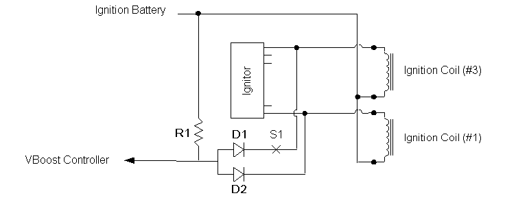
| TBoost - Schematic | ||||||||||||||||
 |
||||||||||||||||
D1, D2 - I used 1 amp general purpose diodes/rectifiers but there is no significant current flow to worry about; a 500ma or less could easily be substituted. I liked the 1 amp devices because they were easy to handle and solder. A diode/rectifier rated at 25 volts or higher is recommended. The following "Radio Shack" diodes will all work just fine and are the same physical size:
R1 - any resistor between 4K and 5K ohms. I actually used a 3.9K 1/2 watt resistor (Radio Shack part no: 271-1123). Again, the current is so minimal that this rating is not really necessary .. a 1/4 watt or less could safely be substituted. S1 - Is a optional toggle switch that will provide normal 6K vboost operation as opposed to the enhanced early opening at 3K RPM (although I really don't think you will find it necessary). Note - The
schematic above indicates the use of the #1 and #3
cylinders; of course #2 and #4 could be substituted also
as the cylinders in each pair are 180 degrees apart.
|
||||||||||||||||
 |
||||||||||||||||
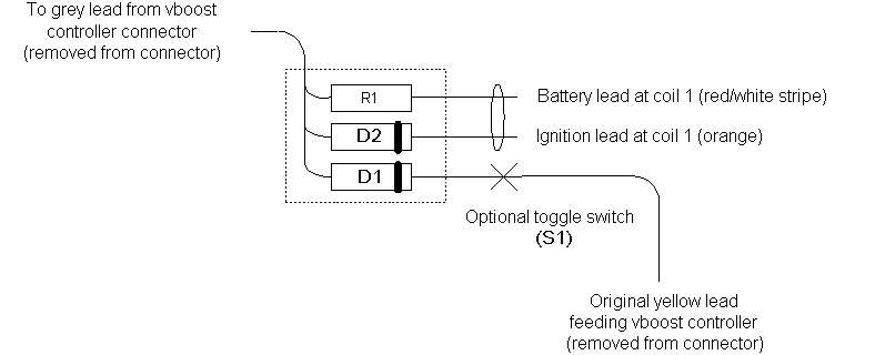
The sketch above shows more realistically how my wiring is laid out. I put all the components in a tube and located it under the left hand scoop next to the vboost controller. The yellow and grey leads were extracted from the original 3 wire connector that feeds the vboost controller (so they would not be damaged .. they can be re-inserted later to return the wiring to its original state). It is "important" to note that this sketch is accurate for a 1990 or later Vmax wiring harness. Earlier models are wired slightly different. (thanks to Mike Cramer for donating his '85 in order to confirm these differences) Specifically, on earlier models, the wiring harness lead that feeds the vboost controller is not "yellow" ...it is "grey". This lead on an earlier model is a multiple of the firing lead from the coil serving cylinder #2 ; on later models it is multiple of the firing lead from the coil serving cylinder #3. This is of no particular importance unless you intend to use the original wiring harness lead to feed the "D1" diode (see sketch). When doing this, the lead feeding "D2" must be from the opposing cylinder of the same bank. As reflected in the photo examples and sketches contained in this document this would be the coil firing cylinder #1 on 1990 and later models ... on 1989 and earlier models the coil firing cylinder #4 must be used. There is one additional "gotcha" in regard to these differences. On all models, the coil serving cylinder #1 is on the left rear side of the motorcycle as is cylinder #1 itself. The front coils are reversed. The coil that actually fires cylinder #4 (right front of the motorcycle ) is physically located on the "left front" side (above cylinder #2). Confused huh ?? No problem ... This simply means that if you are wiring your TBoost up in a manner similar to what is described in this text ... the extra firing lead feeding "D2" (see sketch) and the "battery" lead should be tapped off of coil #1 (left rear) for 1990 or later Vmaxes and off of coil #4 (left front) for 1989 or earlier Vmaxes. Of course, the wiring harness side of the lead feeding the vboost controller (that gets connected to "D1") is grey on early models and yellow on later models (as previously mentioned) but it connects to the TBoost circuitry in the same manner so only the acknowledgment of the color difference is necessary. |
||||||||||||||||
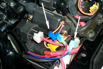
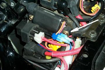
| (photos below) - The two leads going to the #1 (left rear) coil on my '93 are tapped onto existing leads near the coil . I found some neat connectors that provide a great connection and can remain even if all other modification wiring is removed (for pre '90 wiring harnesses we would be using the coil located on the left front side of the bike). | ||||||||||||||||
 |
 |
|||||||||||||||
| This photo shows these unique connectors at the coil . With the actual wiring removed the tap part of the connector can remain with no worries about it being exposed. These are well contained connectors but as Don Seel has recommended .. coating the connection internally will protect against corrosion. | This photo shows the ignition battery and firing lead from the coil all connected up. The wires were housed in a piece of shrink wrap and run down the left side of the frame to the scoop (late models). Early models have it somewhat easier as the left front coil is very close to the vboost controller. | |||||||||||||||
 |
 |
|||||||||||||||
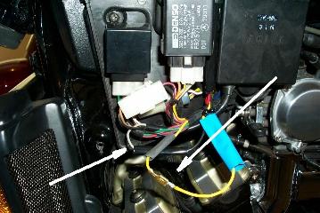
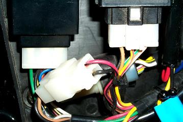
| Here you can see the original yellow and grey leads that were pulled out of the three wire connector that feeds the vboost controller. They can be released easily with a toothpick and can be re-inserted later if desired ... to return the wiring harness to a stock configuration. Currently, the yellow lead connects to a yellow lead that goes into my component tube and connects to the D1 diode. The factory yellow lead is a chain connection to the firing lead for coil #3. If I wanted to add a switch (S1) .. this is where I would put it ... (between these two leads). Of course if you have read the balance of this document you are aware that on pre '90 wiring harnesses the yellow lead is also grey and is a multiple of the firing lead for coil #2. | Although a little "bright" (you will get better photos w/ this is posted permanently) .. this is the connector that the grey and yellow(grey for pre '90) wires were removed from. The yellow (grey for pre '90) came out of the closest end w/ the red and black leads and the grey was removed from the other side that feeds directly into the vboost controller. | |||||||||||||||
 |
 |
|||||||||||||||
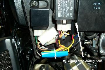
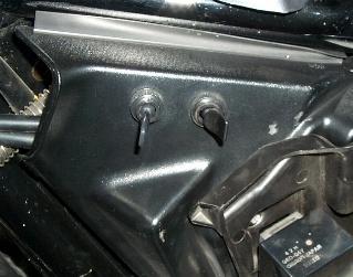
| This photo shows "temporary" wiring on my '93 (I didn't shrink the shrink wrap yet as I am doing some additional testing). My component tube is upright to the left of the vboost controller and will be replaced w/ a rigid tube sealed w/ potting cement.. The extra length on the leads connecting to the factory grey and yellow leads will be shortened and shrink will be "shrunk". The shrink can always be cut off in the future ... the yellow and gray reinserted into the factory connector and no one will know that this modification was ever here. | Here you can see where I mount "my" switches. There is enough room in the fascia on the left side of the bike (the scoop is currently removed). The one in the rear is my "headlamp" switch and the front one I use for various testing (currently an ignition advance switch but easily put into service for the vboost controller or whatever happens to be going on at the time). | |||||||||||||||
Hooking it all up - This is pretty easy to do. Fortunately, the firing lead for coil #3 is already in the wiring harness (coil #2 for pre'90 wiring harnesses). It is the yellow lead feeding fuel pump relay and the vboost controller (colored grey on pre '90 wiring harnesses). There is a male/female combination connector at the vboost controller where this lead and a grey lead (that actually goes into the controller) are connected. I used a tooth pick and released both of these leads from the factory connector so they would not be damaged. I made up a little component tube with the two diodes and the resistor inside of it. All three components are common on one side. I brought a lead out from the common side to connect to the grey vboost controller lead (see the drawing). I brought out another lead from one of the diodes (D1) to connect to the original yellow lead (grey on pre '90 wiring harnesses) that I removed from the factory connector (this was the firing lead for cylinder/coil #3 on late models and coil #2 on pre '90s). If I wanted to connect a switch (S1) I would insert it here between these two leads. I carried two leads ... one from D2 and the other from the resistor up to coil #1 (#4 on pre '90s .. that is located on the left front side of the motorcycle). These connections are shown in the photos above. I used these to tap ignition battery and the firing lead for coil #1 (coil #4 on late models). My temporary "component" tube stands up straight to the left of the vboost controller. When I finish fooling around I will encapsulate these guys and make this all permanent, (I wanted to leave things accessible for a while to make sure nothing was getting warm ... and they aren't .. not even a little) ... Preliminary Testing - I have to tell you that I was a little skeptical about doing this. I had been working on another circuit to provide vboost opening no sooner than 4K RPM. I was afraid that opening it this soon would interfere with my pilot jet tuning. I have been running with normal 6K vboost operation and have enriched my pilot mixture significantly to enhance idle quality and off-idle behavior. I was really afraid that opening the vboost this soon would drive this jetting too rich. This has not been the case .. I have not changed a thing and it works great. It will now take your head off at 3K instead of 6 (this should help my 60' times).. Those that are running normal vboost now and possibly a little too rich on their needles as well will most likely have to back off on their needle setting. Those that are already running open vboost should not have any problem at all. If fact ... if they have added larger PAJ2s to lean out their pilot circuit so that it could live with open vboost then this should no longer be necessary .. they should be able to return to stock or an enhanced pilot jetting configuration. I couldn't live
without this modification even after only having it
installed for such a short time. Hopefully some of you
will try it and if you have any comments or questions
please direct them to the link below or post them on the
Vmax Technical List ... at - Feedback - tclist@qwest.net |
||||||||||||||||