|
|
|
VMAX - Ignition Timing Advance Modification
Overview
Vmax ignitors have a fixed advance curve that is supplemented under light to moderate load conditions. Load is determined via the use of a MAP, (manifold air pressure), sensor and the magnitude of any additional timing advance that the ignitor will apply, (if any), is determined by reading a voltage emitted by the sensor.
The ignitor will apply supplemental advance, (on top of the fixed advance curve), starting as soon as 1500 RPM as long as a vacuum of at least 40mm Hg is exceeded. The amount of advance the ignitor will apply will vary but may be as high as 10 degrees at 9000 RPM, (for a total advance of 43 degrees).
In order to obtain the maximum amount of advance available from the ignitor a manifold vacuum of/or exceeding 80mm Hg must be maintained except in cases where the voltage presented to the ignitor is suitable to make it think that this level of vacuum is present. Fooling the ignitor into believing that this condition exists is the purpose of this modification.
Description of Operation
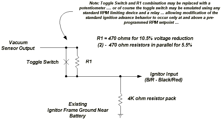
The pressure sensor used on the Vmax is connected with three leads, (ignition battery, ignitor ground and an ignitor sense lead), and a vacuum port which is connected to the intake manifold of cylinder two. Once battery is applied an average sensor will emit 2.0 - 2.3 volts to the ignitor, (key on but without the engine running). An idling Vmax will generally pull anywhere from 170 to 230mm Hg and this will yield approximately 1.7 to 1.6 volts output.
It is important to note that as a greater vacuum is presented to the sensor the output voltage drops and as pressure increases, (less vacuum), the voltage emitted by the sensor increases ... ultimately increasing to the 2.2 volt, (average), range and reflecting normal atmosphere, (no vacuum at all). As a positive pressure is presented to the sensor the output voltage will continue to rise up to a maximum of 4.9 volts. As explained in the Vmax Service Manual, this sensor will respond to pressure variances of -600 to +600mm Hg, (26.6 inches of mercury).
The circuitry described in this modification is inserted between the pressure sensor output and the ignitor sense lead. It's purpose is to reduce whatever voltage is output by the sensor in order to fool the ignitor into thinking that a higher vacuum is present than actually exists. The expected benefit is to be able to have additional ignition advance applied over and above what would have normally been applied by the ignitor using a stock sensor configuration.
For demonstration purposes and for what appears to be practical for normal utilization, this modification offers a design that will reduce the output voltage either 10.5 or 5.5%. It is important to note that a voltage reduction in the range of 10% also appears to the ignitor as a vacuum improvement of 10%. For example ... if you are maintaining 200mm of vacuum and you are using an R1 value, (resistor value, see drawing), of 470 ohms, (for a 10.5 % voltage reduction), and the "toggle switch" contacts are open ..... the ignitor will infact think that a vacuum of 210 mm exists. If the "toggle switch" contacts are closed ... the ignitor will see the voltage normally output by the sensor when reading a vacuum of 200mm.
In practice there is no value in seeking more than the 10.5% reduction R1 value. With an atmosphere output voltage averaging 2.2 volts a 10% reduction would bring the output voltage that the ignitor sees below 2.0 volts. Remember that once the ignitor "thinks" that you are maintaining a vacuum of at least 80mm it is going to apply maximum ignition advance anyhow. 80mm of vacuum will result in a 2.0 voltage output, (approximately), on a stock pressure sensor and thus any voltage reduction greater than 10% would serve no purpose. At 40mm of vacuum and below ... the fixed advance curve only is used. A stock pressure sensor will emit approximately 2.1 volts at 40mm Hg.
The 4K ohm resistor pack that is attached to the sensor output lead provides an impedance sufficiently high enough to have no measurable effect on the output voltage generated by the sensor. It is also sufficiently high enough to protect the circuitry of the ignitor and sensor from damage.
Applications
Applications for this modification are numerous .... the most obvious being the ability to obtain maximum advance from the ignitor at higher RPM when mixture burn time is extremely limited. Being able to enforce this additional advance may make the use of higher octane fuels advantageous in some situations where otherwise their use would be of no value or possibly even reduce performance.
This modification may afford those with modified intake systems the ability to recover vacuum advance benefits that have been lost due to their inability to maintain stock vacuum levels. Also, use of this circuit/modification may facilitate the use of replacement MAP sensors that provide an operating output voltage range higher than that of the stock unit.
Installation Tips
It is not necessary to damage your wiring harness to take advantage of this modification. The ignitor sense lead, (B/R, Black/Red), is easily removed from it's connector, (at the pressure sensor), using a toothpick to release it. Once released you will find that it looks amazingly similar to the common 1/4 inch spade connectors used for miscellaneous wiring. A similar "spade type" female connector is easily slid back into the factory connector and the process can be reversed at anytime in the future. Once my factory sense lead was removed I used a "male" spade fitting and wire to connect it to this circuit. A piece of shrink wrap was placed over the pair and fastened securely to a frame member.
My 4K ohm resistor pack is actually four 1000 ohm resistors that were soldered together and placed in a small fiber tube. Pigtails with connectors were attached to each end of the resistor stack and the container was sealed by pumping it full of silicone/RTV sealer. The toggle switch that I used for this circuit was mounted in the fascia at the front left of the vehicle where the throttle cables enter, (I already had a headlamp switch there anyhow). The toggle switch also provides a mounting point for resistor R1.
The circuit ground was run directly to the frame ground located under the right front portion of the seat near the battery. I connected two wires inside the spade connector that plugged into the ignitor sense lead fitting using one to connect to the resistor pack and the other to run to the toggle switch. All resistors used were 1/2 watt, (although 1/4 watt will do just fine the 1/2 watt variety were much cheaper at Radio Shack ... approx. $1 USD for a pack of 5).
Should this modification need to be reversed in the future the ignitor sense lead can simply be re-inserted into it's original connector and a plastic plug will cover the removal of the toggle switch.
Ignitor Timing Advance Decision Graph
| Manifold Vacuum | Pressure Sensor Output Voltage |
Engine Operating Speed | Engine Load | |
| < 1500 RPM | > 1500 RPM | |||
| < 40mm Hg | > 2.1 | Fixed Advance Curve Only |
Fixed Advance Curve Only | High |
| 40-80mm Hg | 2.0 - 2.1 | Partial Vacuum and Fixed Advance Curve Applied | Medium | |
| > 80mm Hg | < 2.0 | Maximum Vacuum and Fixed Advance Curve Applied | Low | |
Short Term Evaluation
It is difficult to provide an objective evaluation for any modification without using some type of test equipment/facility such as a dyno, 1/4 mile dragstrip etc. Obviously, it is not good practice to depend entirely on the "seat of your pants" as most tuning modifications are not of the type that will produce a gain significant enough by itself to be noticed. Neither is "how soon" you can light your "oil" lamp under hard acceleration a valid testing tool. I have installed this modification on a 1993 Vmax with a stock exhaust, an open and trimmed airbox and a Dynojet stage 1/7 hybrid . As I have the opportunity to collect more substantial testing data/feedback it will be posted on this page.
Clearly .. if you take a good look at the "decision graph" above you will notice that there is a very narrow band of operation for variable vacuum advance to be of any value and with moderate throttle you would generally receive the maximum amount of advance from the ignitor you were ever going to get anyhow. Where this modification seems to be of the most value is apparently for "fat handed" people such as myself that can't resist twisting the throttle wide open on a frequent basis. In this regard I honestly feel that there is a noticeable improvement when starting from a stop and quickly transitioning to wide open throttle. I also feel that there has been an improvement in throttle response when transitioning to wide open throttle while cruising. The only other thing that appears to possibly be affected is a very slight increase in fuel economy but this modification has been installed for such a short period of time it really is premature to make any judgements in that regard. Ever since this '93 was new it would always light the fuel lamp at 100 miles. Only recently and after making some adjustments to the slide needles and jetting have I been able to rise to a "110 - 115" range. Three tanks with this modification have all resulted in the "lamp" lighting between 115 and 120 miles of travel.
I certainly hope others will try this modification and provide feedback. My greatest hope of course is for an extra "horse" or two on my next dyno test ..... and with the toggle switch it will not be difficult to make comparison runs.